HARMONIC RESONANCE
The sympathetic vibration of corrugations caused by buffering the corrugations by a high velocity gas or steam flow.
LENGTH
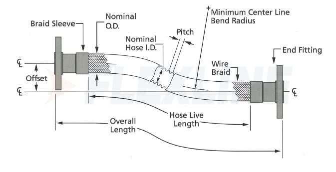
Live: The length of the exposed hose and braid excluding weld rings and fittings; the flexible length of a hose assembly. Also called “exposed length”.
Overall: The total length of the assembly including end fittings. Also called “developed length”.
MOTION
Angular Motion: Motion that occurs when one end of an assembly is deflected in a simple bend. In these applications, care must be taken not to unload the braid by expansion.
Axial Motion: Motion that occurs along the longitudinal axis of the hose so as to compress or expand the length of the assembly. Care should be taken to never use braided assemblies or helical assemblies for this application. Unbraided corrugated assemblies at low pressures and small axial motions are acceptable, alternatively, expansion joints are recommended.
Offset Motion: Motion that occurs when the ends of an assembly are displaced laterally to each other in a plane perpendicular to the longitudinal axis with the ends remaining parallel. The offset radius should never be greater than 25% of the minimum centerline bend radius.
Radial Motion: Motion that occurs when the centerline of the assembly is bent in a circular arc.
Random Motion: Motion that occurs non-cyclically as when an assembly is handled manually. Care should be taken to avoid abrasion and the off-loading of the braid.
Traveling Loops: An installation configuration designed for axial motion or excessive offset motion.
PRESSURE
Pressure Drop: The amount of pressure lost by the medium as it travels through the hose; estimated at 150% higher in metal hose than in new, smooth piping. In long assemblies pressure loss is estimated to be three times that of comparably sized pipe.
Maximum Working Pressure: The maximum operating pressure to which the hose assembly should be subjected, including the momentary surges in pressure, which can occur during service.
Burst Pressure: Actual: The pressure at which the hose assembly can be expected to rupture or the braid fail in tensile. This pressure is determined in a laboratory setting at 70°F and the hose installed in a straight line. Rated: A burst value which may be theoretical or a percentage of the actual burst pressure determined by laboratory test.
Deformation Pressure: The pressure at which the hose corrugations will permanently deform regardless of the external braiding.
Test Pressure (Proof Pressure): The maximum pressure at which a hose can be subjected to without either deforming the corrugations or exceeding 50% of its burst pressure. It is not recommended that hydrostatic testing be conducted above 120% of the Maximum Working Pressure, or 150% of the actual operating pressure of the particular application, whichever is less.
Pulsating Pressure: A rapid cyclic fluctuation in pressure above and below the normal base pressure. Pulsating pressure can cause braid wear.
Shock Pressure: Also called surge pressure or pressure spike; a sudden increase in pressure which creates a shock wave through the assembly. Often causes fatigue failure.
Note: For applications that experience pulsating, shock, or surge pressures, the peak pressures should not exceed 50% of the Maximum Working Pressure and the braid must be tight to the hose with no slack after installation.
VIBRATION
Low amplitude motion occurring at high frequency.
STEAM PIPING GEOMETRY
Piping geometry is a primary driver in designing the routing of steam heating circuits. Steam must be able to freely flow through the jacketing system and contact all heat transfer surfaces. Air and condensate must be efficiently removed from the jacketing to avoid compromising the system’s heat transfer capability. The following design guidelines are helpful for dealing with elevation changes in piping systems:
1.Run circuits downhill. In other words, the steam supply point to the circuit should be at a relatively higher elevation than the condensate return point. This allows the condensate to gravity drain out of the circuit. As a rule, there should not be a vertical rise in the jacketing that would force the condensate to flow uphill. This situation can lead to condensate collecting in the jacketing, which can prevent the free flow of steam to and through the jacketing.
2.Provide a clear path for air removal. Upon startup, the jacketing will be full of air. The air must be removed from the jacketing since air is a good insulator and will prevent the steam from contacting the internal heat transfer surfaces of the jacketing. At pressures above 20 psig, air removal is complicated by the fact that the density of steam is greater than the density of air. Unless there is a clear flow path for the steam to push the air out of the jacketing, buoyancy will drive the air towards high spots in the jacketing. Vertical dead legs in the jacketing system should be avoided since the steam will only compress the air into the dead leg but not be able to remove it.
3.Allow condensate collection in jumpers instead of the jacketing. If the steam jacketing circuit contains more than one heating element, some condensate collection within the circuit is inevitable. It is not desirable for this condensate to collect in the jacketing since it would impede the system’s heat transfer. Rather, it is preferred to allow the condensate to temporarily collect in the jumpers which interconnect the heating elements of the circuit. This will not affect the system’s heat transfer. To allow condensate collection in the jumper, the steam inlet connection on the jacketing must be at a high elevation, and the condensate outlet connection must be at a relatively lower elevation. The jumper must dip below the condensate outlet before entering the steam inlet of the next element. If the connections and/or jumpers are installed in the opposite manner, the entire jacketing will fill with condensate.


